ECT 263 Week 4 Lab Assignment Help | Devry University
- Devry University / ECT 263
- 26 Jun 2019
- Price: $25
- Other / Other
ECT 263 Week 4 Lab Assignment Help | Devry University
Week 4 Lab Question 1
iLab—Frequency Modulation Using Tutor*Tims
(Filename convention: first initial last name FMTT 1.doc
example: jsmithTTFM1.doc)
Part A—Analyzing the Time-Domain Envelope
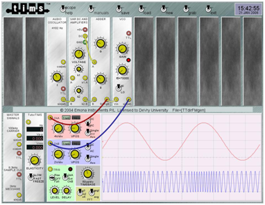
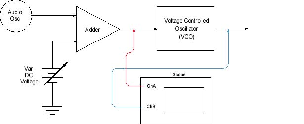
Using Tutor*Tims, create the frequency modulator circuit shown below.
Figure 1: TIMS setup and sample waveforms
Setup an FM modulator in Tutor*Tims similar to Figures
1 and 2 above. Set the controls to produce a reasonable frequency modulated
carrier. Your particular FM waveform will no doubt be somewhat different than
the examples shown here, and for that matter, will be different than your
classmates’. In fact, it is a requirement that each student do his or her own
work and submit his or her own report.
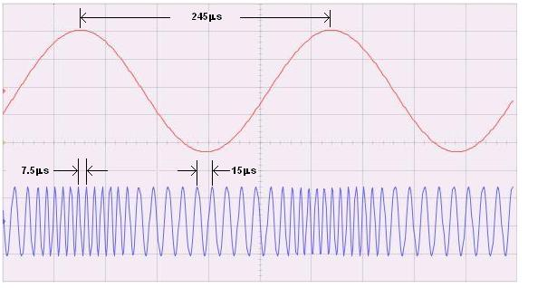
Below in Figure 3 is an example of a typical frequency
modulated carrier. There are several variables that you can use to adjust your
FM signal. The audio oscillator frequency, the DC offset, the gain of the adder
module, the gain of the VCO module and the center frequency (f0) of
the VCO module. All of these can be manipulated to produce your own unique FM
signal.
Figure 3: Sample FM signal annotated to show the periods of the audio wave, the carrier at its highest frequency point, and the carrier at its lowest frequency point.
Given these values of period at the highest frequency
point, period at the lowest frequency point and period of the audio frequency,
determine the following.
-
· fMAX
· fMIN
· fM
·
· m
Continuing with this example, here are the solutions. You will use the accompanying template to submit your own unique FM signal waveform and its respective values and calculations.
A couple things worth noting in this example.
- Whereas a
modulation factor of 8.1 might seem somewhat high, unlike in AM where a
modulation factor greater than one would result in over modulation, serious
distortion and adjacent channel interference, in wide band FM it would be
quite acceptable.
- If you
look carefully, in Figure 1 you will see that the center frequency of the
VCO is set to 70kHz. Why then would the nominal carrier frequency (which
one would expect to be midway between fMIN and fMAX)
be 100 kHz? [Because the “Var DC and Amp” module is introducing some DC
offset which results in an overall frequency shift.]


 USA
USA  India
India
Question Attachments
1 attachments —