ECT 122 Week 3 Lab Assignment Help | Devry University
- Devry University / ECT 122
- 11 Jan 2019
- Price: $10
- Other / Other
ECT 122 Week 3 Lab Assignment Help | Devry University
Part 1
1. Create the circuit shown in Figure 3.1 from this week’s course shell lecture in Multisim. For the resistors, be sure to use RATED VIRTUAL components. Your circuit should look something like the one below.
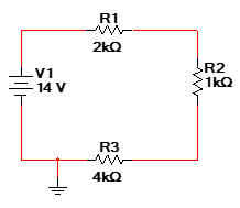
2. Add digital multimeters (DMM) and wattmeters to your circuit so that you can measure the voltages across the three resistors, the current in the circuit and each resistor’s power.
Indicate the values below:
VR1 = ___________ VR2 = ___________ VR3 = ___________
I = ____________ PR1 = ___________ PR2 = ___________
PR3 = ___________
Change the positions of the resistors. For instance, connect R3 directly to the positive side of the DC source. Simulate the new circuit. Do any of the parameters above change? Yes/No
Why or why not?
3. Create the circuit shown in Figure 3.2 from this week’s course shell lecture in Multisim. For the resistors, be sure to use basic resistor components with a tolerance of 5%. Your circuit should look something like the one below:
Simulate the complete circuit and indicate the measured values in the table below:
|
VR1 = |
IR1 = |
PR1 = |
|
VR2 = |
IR2 = |
PR2 = |
|
VR3 = |
IR3 = |
PR3 = |
|
VR4 = |
IR4 = |
PR4 = |
Do the values exactly match what is shown in this week’s lecture? Yes/No
Why or why not?
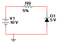
4. Create the circuit shown in Figure Q1 from this week’s course shell lecture in Multisim. For the resistor, be sure to use a basic resistor with a tolerance of 5%. The resistance value will come from the calculation from the practice quiz problem. You can find the zener diode under the Diodes group and DIODES_VIRTUAL family. Choose the ZENER_VIRTUAL. Your circuit should look something like the one below.
What was the measured voltage across the zener diode?
VD1 = ________________
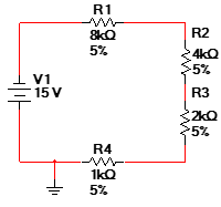
1. Simulate the circuit in this week’s course shell practice quiz problem 7/8. The circuit should look something like the following:
Fill in the table below with the simulation results.
|
VR1 = |
IR1 = |
PR1 = |
|
VR2 = |
IR2 = |
PR2 = |
|
VR3 = |
IR3 = |
PR3 = |
|
VR4 = |
IR4 = |
PR4 = |
Compare the simulation results to the calculated parameters from this week’s practice quiz. Are they the same?
Part 2
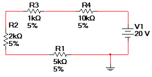
1. Repeat the steps above for circuit shown in this week’s course shell practice quiz problem 9/10 WITH THE FOLLOWING CHANGE: HALVE all the resistor values (for instance the 8kΩ resistor becomes 4 kΩ, etc) and DOUBLE the supply voltage to 10 V.
|
Voltage |
Current |
Power |
Wattage Rating (1/8, 1/4, 1/2) |
|
VR1 = |
IR1 = |
PR1 = |
|
|
VR2 = |
IR2 = |
PR2 = |
|
|
VR3 = |
IR3 = |
PR3 = |
|
|
VR4 = |
IR4 = |
PR4 = |
|
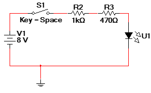
2. An electronics student needs to design a series circuit that consists of an 8 V DC source, a switch, two resistors, and a light-emitting diode (LED). The switch will open and close the connection from the source to the LED so that the LED turns on and off. The student has come up with the following circuit design:
An LED illuminates when the required amount of current passes through it. The required ON current is typically found on the datasheet of an LED. Multisim LED’s show the required ON current in the value tab of the component. The following components should be used:
|
Device |
Group |
Family |
Component |
|
Switch |
Electro_Mechanical |
SUPPLEMENTARY_CONTACTS |
SPST_NO_SB |
|
LED |
Basic |
RATED_VIRTUAL |
LED_RED_RATED |
|
Resistors |
Basic |
RESISTOR |
1kΩ, 470Ω |
The problem is that when the switch is
closed (space bar pressed) to make connection from the 8V source to the rest of
the circuit, the LED does not turn on.
What is keeping the LED from turning on
when the switch is closed?
What change(s) can the student make to resolve the issue? Assume that the source or LED CAN NOT be changed.



 USA
USA  India
India