ECT 122 Week 2 Lab assignment Help | Devry University
- Devry University / ECT 122
- 11 Jan 2019
- Price: $10
- Other / Other
ECT 122 Week 2 Lab assignment Help | Devry University
Part 1
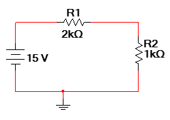
1. Create the circuit shown in Figure 2.4 from this week’s course shell lecture in MultiSim. For the resistors, be sure to use RATED VIRTUAL components. Your circuit should look something like the one below.
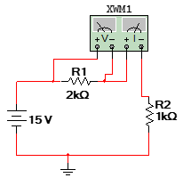
1. Add digital multimeters (DMM) to your circuit so that you can measure the voltages across the two resistors and the current in the circuit
2.
Double click each of the meters to display their
faces. Click the run button to start simulation. You will be able to see the
voltage reading across each of the resistors. Indicate the values below:
VR1 (voltage across resistor R1) =
___________ VR2 (voltage
across resistor R2) = __________
Note: be sure to use the correct units.
3.
Add a third meter to measure current in the
circuit.
I = _________________
Once you double-click on the Wattmeter, you will be
able to see the display of the device. Run the simulation to measure the power
absorbed by the resistor. Note that the Wattmeter requires two sets of inputs.
One set of inputs, marked V, is set up to measure voltage of the device of
interest. The other set of inputs, marked I, is set up to measure current going
through the component of interest. Note again that the path of the circuit must
be broken to force the flow of current through the meter. Repeat these
connections with a second Wattmeter for resistor R2. Simulate the complete
circuit and indicate the measured power values for each resistor:
PR1 = _______________ W PR2 = _________________W
6. Determine the connections necessary to measure the power absorbed by both resistors. Make the connections and simulate the circuit. Does the value match what is shown in this week’s lecture? Yes/No
8.
With the simulation stopped, double-click R1 to
view the parameters of the rated resistor. Note that power rating of the
component is the default 250 mW. This power rating is much higher than the
value that you should have observed in part 5 above. Now change the power
rating of the device to the value just less (perhaps 5 mW less) than what was
calculated in the course shell lecture (which should match the value you
observed in part 5 above). Indicate the
power rating you chose:
Adjusted power rating of R1 =
________________W
Restart the simulation and wait about five
seconds. What happened?
Why do you think this occurred?
Change the power ratings of both resistors
to the value recommended in this week’s course shell lecture. Restart the
simulation. What happened?
What is different than the last simulation?
Part 2
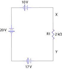
1. Repeat the steps above but create the circuit to verify the answer to this week’s course shell lecture quiz problem 8 (circuit below). Replace the picture with a snapshot showing the complete circuit including a voltmeter indicating the voltage across resistor R1.
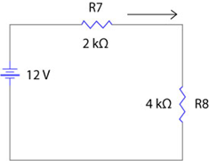
2. Reference problem 9/10 from this week’s lecture quiz (circuit below). Repeat the problem analysis for a circuit where R7 has been replaced by a 3 kΩ resistor and R8 has been replaced with a 6 kΩ resistor.

|
Resistor |
Voltage |
Current |
Power |
Wattage Rating (1/8, 1/4, 1/2) |
|
R7 |
|
|
|
|
|
R8 |
|
|
|
|
3. Create the circuit in MultiSim and verify your values. Take a screenshot showing all necessary meter displays that justify your answers in the above table.


 USA
USA  India
India
Question Attachments
0 attachments —